Deadfront Switchboard – Marking and Application Guide
December, 2021
PREFACE
UL developed the Dead-Front Switchboard Marking Guide for code authorities, electric utilities, contractors, installers, users, designers, and other interested parties to aid in understanding deadfront switchboards and the applicable codes and standards in order to facilitate a reasonably safe and code-compliant installation of switchboards used in ordinary locations, rated 1000 volts or less. These switchboards are intended to be installed in accordance with the National Electrical Code® (NEC ®) and their Certification (listing). These markings are required by UL 891, and are part of the Certification (Listing).
The Table of Contents links to the main headings. The Index gives an alphabetical list of specific items and the section numbers where information about them can be found. Marking and Application guides are available for Panelboards and Molded Case Circuit Breakers at http://www.ul.com/markingguides.
Complete information regarding the provision of markings and instructions for these switchboards is contained in the Standard for Switchboards, UL 891. References to the National Electrical Code® (NEC ®) are to the 2020 edition.
UL Marking and Application Guides are updated as necessary due to new product development, changes in the codes, or the need for clarification. To confirm the current status of any UL Marking Guide, please consult the Code Authorities page of the UL Web Site at; www.ul.com/codeauthorities or www.ul.com/markingguides.
Your comments or suggestions are welcome and appreciated. They should be sent to:
UL’s Codes and Regulatory Services Department
ulregulatoryservices@ul.com
TABLE OF CONTENTS
- PREFACE
- INTRODUCTION
- 1. GENERAL INFORMATION
- 2. GLOSSARY
- 3. ELECTRICAL RATINGS
- 4. PHASE IDENTIFICATION
- 5. SERVICE EQUIPMENT
- 6. GROUND-FAULT PROTECTION
- 7. TAPS
- 8. TERMINALS
- 9. BRACING
- 10. SYSTEM COORDINATION
- 11. VOLTAGE DROP
- 12. CONDUIT ENTRY
- 13. ENCLOSURE TYPES
- 14. MULTIPLE SOURCES
- 15. BARRIERS
- 16. SWITCHBOARDS WITH PROVISIONS FOR CORD CONNECTIONS
- 17. FIELD INSTALLATION OF DEVICES
INTRODUCTION
USE OF THIS GUIDE
This guide is intended to assist code authorities, designers, and installers in determining the suitability of deadfront switchboards in a particular installation and use, and to address concerns related to fire, shock, and mechanical hazards.
Products are Certified, Listed or Classified by UL under an appropriate product category. A four-letter code (shown in parenthesis) following every category title in this guide is the UL product category code designation.
Each UL product category code provides a direct link to the guide information for the product category. The guide information includes the scope of the products covered, information relating to limitations or special conditions applying to the product, the requirements used for the investigation of the products, installation and use information, and information on product markings and the UL Mark to be used on the product. Additional information on marking requirements can be found in the guide information for Dead-Front Switchboards (WEVZ), which is located on UL Product iQ at UL.com/piq.
The product markings identified in this Guide do not include every possible marking that could be provided either on a product or in its installation or operation instructions. The purpose of this Guide is to provide you with an indication of the type of text and location of markings that address features that may be critical in determining if a product is certified and/or if it is installed correctly. Refer to the specific guide information for the product category for additional marking information.
The numbering for code sections used in this document may change as the specific code is updated.
INFORMATION ON CERTIFICATION, LISTING AND CLASSIFICATION
Most codes and regulations require the certification of power distribution equipment to applicable safety-related standards. They also may require this equipment to be certified to energy performance standards as well. Products that are certified to safety-related standards have been evaluated with regard to all reasonably foreseeable safety-related hazards, including fire, electrical shock and mechanical hazards. Such products are termed “UL Listed.” Products that are certified to a limited range of hazards, or for use under specific conditions are termed “UL Classified.” Alternatively, any of these products can be “UL Certified” and bear the UL Certification Mark
It is important to distinguish the difference between or “UL Listed” and “UL Classified” and the relation these terms have with the term “listed,” as used in various codes. The term “listed” in the codes generally indicates that the product is required to be evaluated in accordance with the appropriate standard(s) by an independent third party certification organization such as UL. The term “listed” in the codes should not be confused with the term “UL Listed,” as explained above. It is important to recognize that not all certification agencies make this distinction in their certification services.
INFORMATION ON UL MARKS
There are several types of UL Marks that can be found on power distribution equipment. General information on each of these Marks is provided below. Each has its own specific meaning and significance. The only way to determine if a product has been certified by UL is to look for the UL Mark on the product itself.
The UL Mark on a product means that UL has tested and evaluated representative samples of that product and determined that they meet the requirements in the applicable standard(s). Under a variety of UL programs, certified products are periodically checked by UL at the manufacturing facility to determine that they continue to comply with the standard(s).
The UL Marks may only be used on, or in connection with products certified by UL, and under the terms of a written agreement between the manufacturer and UL.
IDENTIFICATION OF UL CERTIFIED PRODUCTS
Launched in mid-2013, the enhanced UL Certified Mark can be used on both UL Listed and Classified products and is intended to make it easier and simpler for stakeholders to understand the scope of UL’s certifications of a specific product. The enhanced UL Certified Mark makes it possible to bundle multiple UL certifications for multiple geographies into a single Mark design. Today, this mark is used for products certified to U.S., Canadian, European and Japanese requirements. This Mark utilizes a unique identifier to enable stakeholders to UL Product iQ™ at UL.com/piq to quickly to review detailed certification information.
All currently existing versions of UL’s Listing and Classification Marks remain valid and should continue to be accepted as an indication of certification.
UL expects the transition to the enhanced Mark to happen over time, so you may not see it in the immediate future. For more information on this important development, please go to www.ul.com/markshub > Resources. Access to the Marks Hub is free and open to all regulators, but registration to use it is required.
UL Listing Mark
This is one of the most common UL Marks. If a product carries this Mark, it means UL found that representative samples of this product met UL’s safety requirements. These requirements are primarily based on UL’s own published Standards for Safety, or other recognized third party standards. The UL Listed Mark includes the UL symbol, the word “Listed,” the product or category name, and a control number assigned by UL.

UL Classification Mark
This Mark appears on representative samples of products that UL has evaluated but only with respect to specific properties, a limited range of hazards, or suitability for use under limited or special conditions. The UL Classified Mark includes the UL symbol, the word “Classified,” a statement of the scope of evaluation, the product or category name, and a control number assigned by UL.

Field Evaluations
You may encounter situations in which you are unable to determine if a product has been listed by a third-party organization. Or in other situations you might encounter a product bearing a listing label that may have been modified in the field, and now you question whether or not the product still complies with the applicable standard. UL offers a field evaluation service that provides data to assist you in making your decision whether to accept the product and/or approve the installation. Anyone directly involved with a product – including manufacturers, owners, contractors, and regulatory authorities – can request a Field Evaluation. Detailed information for this program can be found on UL’s Web site at www.ul.com/field.
-
GENERAL INFORMATION
UL Certifies (Lists) manufacturers of dead-front switchboards under the category of “Dead-Front Switchboards” (WEVZ) on UL Product iQ™ at UL.com/piq.
UL Product iQ also contains names of manufacturers who are authorized to label equipment similar in appearance to dead-front switchboards under the following categories:
Circuit Breaker and Metal-Clad Switchgear — over 600 volts (DLAH)
Switchgear Assemblies, Metal Enclosed, Low-Voltage Power Circuit Breaker Type (WUTZ)
The evidence of Certification (Listing) is the UL Certification (Listing) Mark on the product. The Certification (Listing) Mark for switchboards includes the name and/or symbol of UL, together with the word “Certified” or “Listed,” a control number and one of the following product names as appropriate: “Dead-Front Switchboard Section,” “Switchboard Interior,” or “Switchboard Enclosure.”
The Certification (Listing) Mark for Dead-Front Switchboard Sections contains the marking “_____________of ___________,” in which the first space is marked with a number indicating the position that the section occupies in the series of sections which constitute the switchboard, and the second space is marked with the total number of sections (both Certified (Listed) and non-Certified (non-Listed)) in the switchboard. A single section switchboard is marked 1 of 1. The section on the left side when facing the front of the switchboard is marked as position one of the series.
A switchboard section mounted on top of one or more sections is marked “__________ T” where the blank is filled with the number of the initial section covered. A switchboard enclosure (pull section) may be included in the numbering sequence if it is located at either end of the switchboard. The pull section is included in the numbering sequence if located between switchboard sections.
A switchboard section omitting one side is marked to indicate the catalog number of a separate side panel that should be ordered, or the catalog numbers of stock sections to which it is intended to be connected.
The Certification (Listing) Mark is applicable only to the section so marked; it does not cover other sections included in the complete switchboard. A switchboard may be shipped from the factory incorporating both Certified (Listed) and non-Certified (non-Listed) sections. The non-Certified (non-Listed) sections have not been evaluated by UL.
The basic Standard used to investigate products in this category is the Standard for Switchboards, UL 891.
Switchboard markings may be molded, die-stamped, paint stenciled, stamped, etched metal that is permanently secured, or on a label secured by adhesive. Some markings may be located on a wiring diagram in a pocket on the switchboard.
-
GLOSSARY
- ACCESSIBLE, FRONT – An enclosure in which incoming and outgoing field termination points are accessible from the front. Other connections shall be permitted to be rear or side accessible. If necessary, a limited number of devices shall be permitted to be removed to achieve this accessibility.
- ACCESSIBLE, REAR – An enclosure in which all incoming and outgoing field termination points are accessible from the rear. Other connections shall be permitted to be front or side accessible. If necessary, a limited number of barriers or covers shall be permitted to be removed to achieve this accessibility.
- AMPACITY – The current in amperes a conductor can carry continuously under the conditions of use without exceeding its temperature rating.
- BARRIER – A partition for the insulation or isolation of electric circuits or electric arcs.
- BONDING – The permanent joining of metallic parts to form an electrically conductive low impedance path that will assure electrical continuity and the capacity to conduct safely any current likely to be imposed.
- BUS – A conductor, or group of conductors, that serves as a common connection for two or more circuits.
- BUS, BRANCH – A bus that originates at a section bus and terminates in one or more overcurrent devices.
- BUS, GROUND – A bus to which the equipment grounding conductors from individual pieces of equipment are connected and which, in turn, is connected to the grounding electrode conductor at one point. It provides a continuous ground in multiple equipment sections through which it passes. See Figure 2.1.
- BUS, NEUTRAL – A bus having the appropriate number of terminals to provide for the connection of the neutral line and load conductors. See Figure 2.1.
- BUS, SECTION – That portion of the bus structure that serves one or more overcurrent devices in the switchboard section and comprises that part of the bus between the supply bus and branch bus. See Figure 2.1.
- BUS, SPLICE – A bus that electrically connects switchboard sections. See Figure 2.1.
- BUS, SUPPLY – A bus that is intended primarily for conducting electric power from the source to the main section of a switchboard. See Figure 2.1.
- BUS, THROUGH – A bus that extends through a switchboard section. It is sometimes called a horizontal, cross or main bus. See Figure 2.1.
- CIRCUIT BREAKER – A device designed to open and close a circuit by non-automatic means, and to open the circuit automatically on a predetermined overcurrent, without injury to itself when properly applied within its rating.
- CIRCUIT BREAKER, MOLDED CASE – A circuit breaker which is assembled as an integral unit in a supporting and enclosing housing of insulating material.
- CONTINUOUS CURRENT – The amount of current a conductor, a device or a piece of equipment can carry continuously for an indefinite period of time without exceeding its allowable temperature rise.
- CURRENT RATING – The designated maximum direct or alternating current in rms amperes at rated frequency that a device can carry continuously under specified conditions.
- DEAD-FRONT SWITCHBOARD – A switchboard which has no exposed live parts on the front.
- DEVICE – A component of an electrical system that is intended to carry or control, but not utilize, electrical energy.
- DISCONNECTING MEANS – A device, or a group of devices, or other means by which the conductors of a circuit can be disconnected from their source of supply.
- DOUBLE-ENDED SWITCHBOARD (Multiple Source) – A switchboard construction that provides for the connection of two supply sources, such as a utility service and an on-site generator. See Figures 2.2 and 2.3 for typical examples.
- FUSE – A protective device which opens by the melting of a current-sensitive element during specified overcurrent conditions.
- FUSIBLE SWITCH – A switch in which one or more poles have a fuse in series in a composite unit.
- I2t (AMPERE SQUARED SECONDS) – An expression related to the circuit energy as a result of current flow. The “I2” stands for the square of the effective (rms) let-through current and the “t” stands for the time of current flow in seconds. “I2t” is a common expression for the circuit energy between the initiation of the fault current and the clearing of the circuit.
- INLET – A permanently mounted plug intended to receive power from a cable connector.
- INTERLOCK – An electrical or mechanical component actuated by the operation of a device or other means, with which it is directly associated to govern succeeding operations of the same or allied devices.
- INTERRUPTING RATING – The highest current at rated voltage that a device is intended to interrupt under standard test conditions.
- MAIN DEVICE – A single device that disconnects all ungrounded conductors, other than control power conductors when used, from the supply bus. See Figure 2.1.
- MAIN SECTION(S) – A portion of a switchboard where the main or service disconnect device(s) is located. The section shall also be permitted to contain utility meters or other instruments. Incoming line conductors may be terminated in this section. See figure 2.1.
- NEUTRAL – Neutral refers to a conductor (when one exists) of a polyphase circuit or single-phase, 3-wire circuit which is intended to have a voltage such that the voltage differences between it and each of the other conductors are approximately equal in magnitude and are equally spaced in phase, such as:
- the center point of a wire connected system,
- the midpoint of a 3-wire, single phase system,
- the midpoint of one side of a delta connected system.
- OUTLET – A device that is intended to provide power to an inserted plug, and that is installed as a fixed receptacle on equipment.
- RATING – A designated limit of operating characteristics based on definite conditions.
- RATING PLUG – A self-contained portion of a circuit breaker that is interchangeable and replaceable in a circuit breaker trip unit by the user. It sets the Rated Current (In) of the circuit breaker.
- SERVICE EQUIPMENT – The necessary equipment, usually consisting of a circuit breaker or switch and fuses, and their accessories, located near the point of entrance of supply conductors to a building or other structure, or an otherwise defined area, and intended to constitute the main control and means of cutoff of the supply.
- SHORT-CIRCUIT CURRENT RATING – The maximum RMS available current to which a device can be connected. The rating is expressed in amperes and volts.
- SWITCH – A device, manually operated, unless otherwise designated, for opening and closing or for changing the connection of a circuit.
- SWITCHBOARD – A large single panel, structural frame or assembly of panels or structural frames on which may be mounted, on the face or back or both: switches, overcurrent, and other protective devices, buses, and instruments.
Note: Switchboards may be accessible from the rear as well as from the front and are not intended to be installed in cabinets. - SWITCHBOARD ENCLOSURE – An enclosure that encloses one or more switchboard sections or switchboard interiors, or provides auxiliary wiring space for an adjacent switchboard section.
- SWITCHBOARD INTERIOR – The interior part of a switchboard intended to be installed in a switchboard enclosure to become the equivalent of a switchboard section.
- SWITCHBOARD SECTION – That portion of a switchboard that is prevented by the structural framework from being physically separated into smaller units.
Note: Framework that is welded or joined with steel rivets over 1/4 inch (6.4 mm) in diameter is considered to constitute a single section. However, framework that is joined with one-way (tamper-proof) bolts is not considered to constitute a single section. An assembly consisting of an enclosure and terminal blocks or bus bars is considered to be a switchboard section. - SYMMETRICAL CURRENT – Alternating current having no offset or transient component and, therefore, having a wave form essentially symmetrical about the zero axis. Symmetrical current is expressed in terms of rms A.
- TAP – A terminal or provision for a terminal intended for field wiring that is located on the supply side of the service disconnecting means, for uses permitted by the installation rules of the country of installation.
Figure 2.1: Typical dead-front switchboard layout
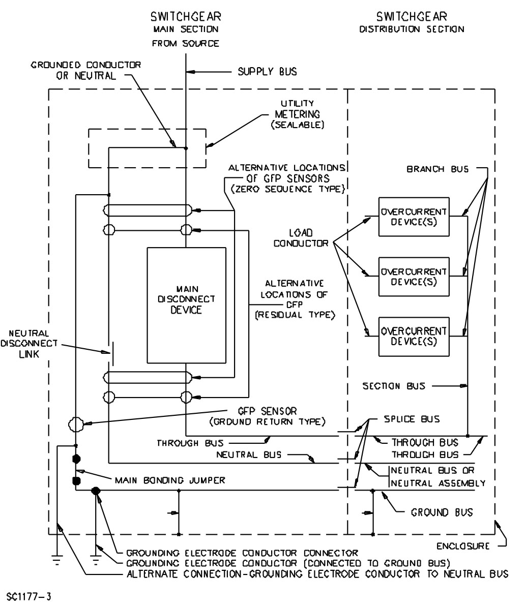
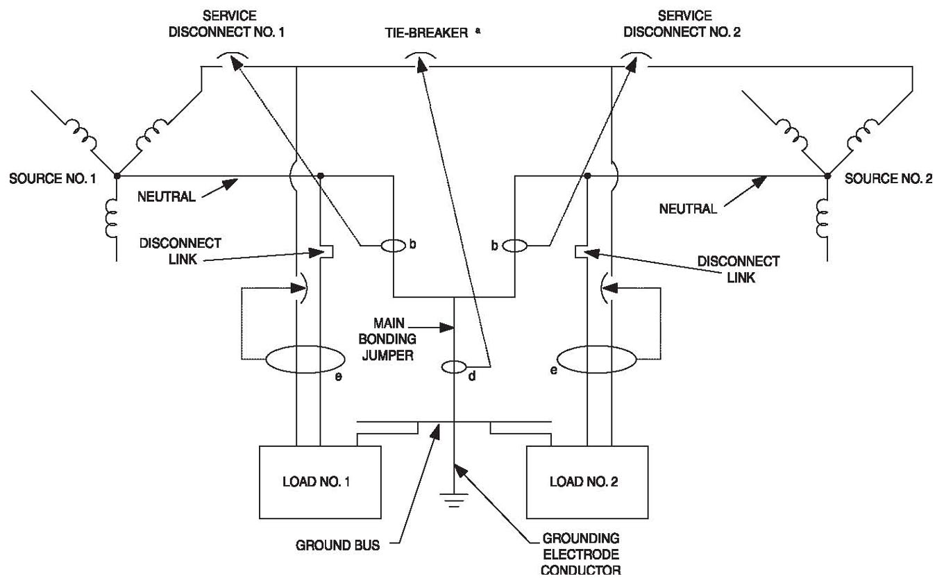
Figure 2.2: Typical double-ended switchboarda
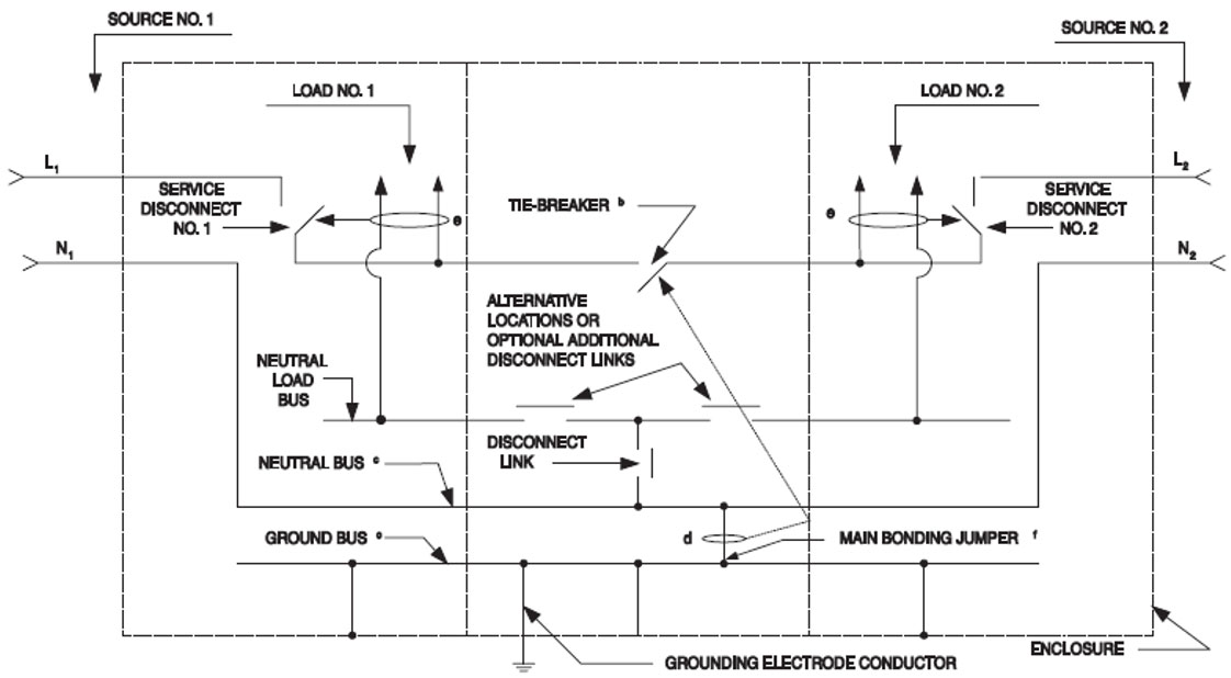
aOther variations are possible.
bTie-breaker disconnect (not a circuit breaker marked “Line” and “Load,” nor a fused switch).
cThe neutral bus and ground bus may be combined if ground-return type ground-fault protection is not used and the sections are marked “Suitable only for use as service equipment.”
dGround-return type ground-fault protection sensor.
eZero sequence or residual type ground-fault protection sensor.
fSize of main bonding jumper based on largest service disconnect.
Figure 2.3: Typical double-ended switchboard
aTie-breaker disconnect (not a circuit breaker marked “Line” and “Load,” nor a fused switch).
bAdditional ground-return type ground-fault protection sensors are utility interlocked with the sensor described in note d so as to function only when a fault current is also sensed by the sensor described in note d.
cSize of main bonding jumper based on largest service disconnect.
dGround-return type ground-fault protection sensor.
eZero sequence or residual type ground-fault protection sensor.
-
ELECTRICAL RATINGS
General
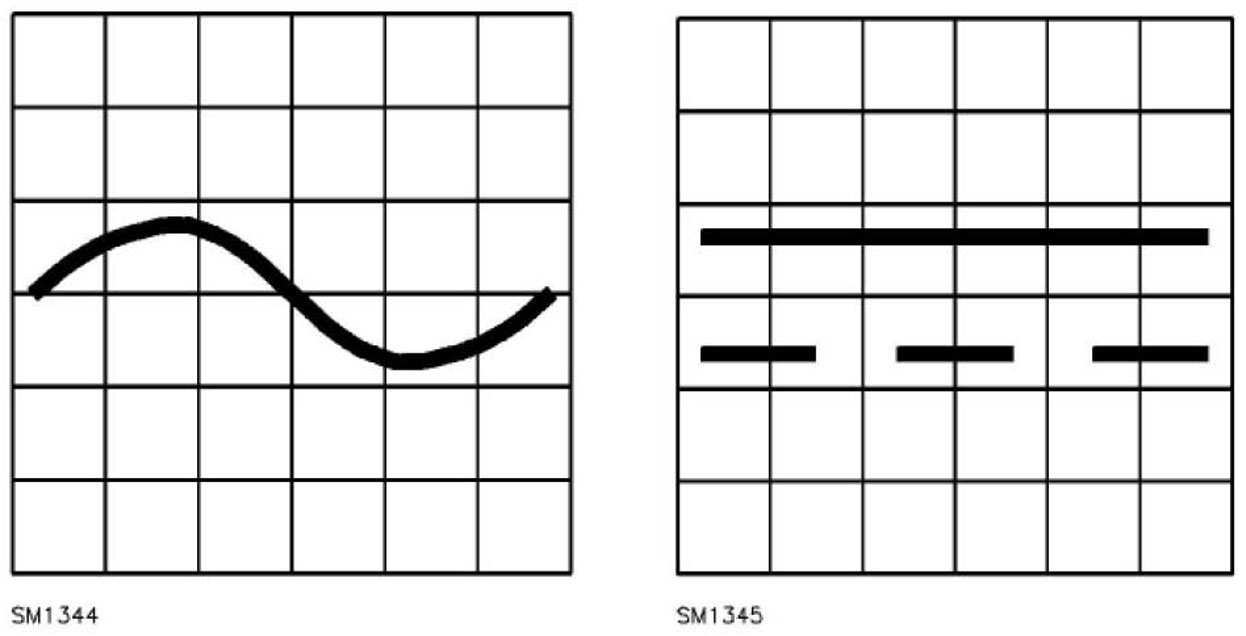
The electrical rating includes voltage, current, frequency and short-circuit current ratings. An alternating current rating includes the number of phases, if other than single phase. Voltage ratings are followed by the symbol for alternating current and/or the symbol for direct current. See figure 3.1.
Figure 3.1 AC and DC voltage symbols
A switchboard section or interior with provisions for connection to two or more supply sources is marked to indicate the current and voltage ratings for each supply source.
A switchboard section or interior with provision for connection to an external source of control circuit power, are marked to identify that purpose. The current and voltage ratings for the power source are marked or indicated on a wiring diagram.
Location
A switchboard section is marked with the electrical rating where it will be visible without removing any cover or trim.
A switchboard interior is marked with the electrical rating where it will be visible before or after a cover is installed.
A switchboard enclosure that is marked for use with a particular switchboard interior is marked with the electrical ratings of the switchboard interior, unless the switchboard interior rating will be visible, after installation, without removing any cover.
Voltage Rating
A switchboard section or interior is rated no more than 1000 volts.
A switchboard section or interior may be marked with several alternative voltage ratings.
A switchboard section or interior that is designed for use on supply circuits involving two different voltages is marked with a combination voltage rating, e.g., 208Y/120, 480Y/277.
If a switchboard section or interior contains a transformer with a secondary circuit that leaves the section or interior, the transformer secondary voltage rating is marked.
Current Rating
Each switchboard section or interior is marked with the current rating of the supply bus and section bus; and, in addition, with the rating of the through or splice bus supplying the next section or interior, if the through or splice bus current rating is less than the current rating of the supply bus.
The adequacy of the supply, through, splice or section bus current rating with respect to the calculated load current (using the appropriate diversity factors in Article 220 of the NEC®) can only be determined at the time of final installation.
If the ampacities of the various phase bus bars, including the neutral bus bar, are not identical, the current rating markings of each bus bar and terminal are provided.
Short-Circuit Current Rating
Each switchboard section containing devices other than a transformer and associated wiring or interior is marked with the following information:
- The words “Short-Circuit Current Rating” and the dc or rms symmetrical short-circuit current rating in amperes as noted in Table 3.1. If the switchboard section or interior contains meter mounting equipment other than that intended for use with current transformers, the phrase “Watthour meter not included in the short-circuit current rating” is also provided.
- The maximum dc or rms voltage rating for each short-circuit current. (Since the ability of an overcurrent protection device to open on fault currents is affected by the voltage rating of the circuit, a switchboard may have several different short-circuit current ratings, each associated with a specific voltage rating.)
- A statement that the short-circuit ratings are limited to the lowest short-circuit rating of (1) any switchboard section connected in series, (2) any installed circuit breaker or fused switch other than those located in a control circuit, (3) the short-circuit rating marked on the switchboard of any installed combination series-connected circuit breaker, or (4) any installed panelboard having a marked short-circuit rating.
- A statement that additional or replacement devices –other than fuses – are to be of the same manufacturer, type designation, and equal or greater interrupting rating. This may be accomplished by specific reference to the device if the interrupting rating of the device is not less than any marked short-circuit current rating of the switchboard. The ampere rating of the device is also included if the short-circuit rating varies with the ampere rating of the device. For a fuse, the class of fuses is specified.
- If applicable, identification of the combination of the integral or remote main and branch circuit overcurrent devices that are required when applying the marked short-circuit current rating.
Table 3.1: rms symmetrical or DC short-circuit current rating
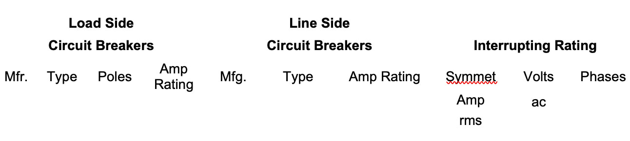
Amperes 5,000 25,000 75,000 7,500 30,000 85,000 10,000 35,000 100,000 14,000 42,000 125,000 18,000 50,000 150,000 22,000 65,000 200,000 Figure 3.2 shows an example of a switchboard marking providing information for installation of circuit breakers having a lower interrupting rating than the short-circuit current rating of the switchboard. Circuit breakers are acceptable for use above their marked interrupting rating if used on the load side of a specific overcurrent device. (Blank spaces would be filled with appropriate information.)
Table 3.2: Sample short-circuit current rating
- “The short-circuit current rating of this switchboard is equal to the lowest interrupting rating of any installed circuit breaker or fused switch, but not more than___________rms symmetrical amperes at __________volts, 3-phase, or ___________rms symmetrical amperes at __________volts, single phase”; and
- “The interrupting rating of a circuit breaker is 5,000 rms symmetrical amperes and for a fused switch is 10,000 rms symmetrical amperes”, or as marked on the device, except for the following series combination ratings:
A load side circuit breaker may be a branch, sub-main, or an integral main used on the load side of a remote main. A line side circuit breaker of fused switch may be a sub-main, integral main, or a remote main. This series combination short-circuit current rating shall not exceed the interrupting rating of the line side circuit breaker of fused switch.
If the short-circuit current rating of a switchboard is dependent upon the use of a specific overcurrent device ahead of the switchboard, the switchboard is marked “When protected by _______ ampere maximum Class _______ fuse or ________Type circuit breaker rated no more than _______ amperes, this switchboard is suitable for use on a circuit capable of delivering no more than ________ rms symmetrical amperes volts maximum.” The second blank space is filled with the fuse type designation (CC, G, J, L, RK1, RK5 or T). The third blank space is filled with the name of the circuit breaker manufacturer and the type designation.
The marking indicates only the type of overcurrent device(s) with which the switchboard has been tested.
Switchboards with inlets are marked with an additional short circuit rating where a different rating exists when connected to the inlets.
-
PHASE IDENTIFICATION
Unless marked otherwise, the phase arrangement of the supply, through and section bus bars in a 3-phase switchboard, but not including the connections to meter sockets, is A, B, C from front to back, top to bottom, or left to right as viewed from the front of the switchboard section or interior.
-
SERVICE EQUIPMENT
Switchboards suitable for use as service equipment are provided with one of the following markings:
- “Suitable for use as service equipment” or
- “Suitable for use only as service equipment.”
Additional wording that places limitations on the use of the switchboard when used as service equipment may be added to either of the markings above for specific constructions. Typical wording that may be added is “… when no more than six main disconnecting means are provided.”
Unless otherwise indicated below, a switchboard that is marked for use as service equipment will contain from one to six service disconnecting means, service overcurrent protection, a neutral disconnecting link, a main bonding jumper and a grounding electrode conductor terminal.
The section or sections of a multi-section switchboard that contain the main bonding jumper, the grounding electrode conductor terminals and the neutral disconnecting means will be marked.
The main bonding jumper, the grounding electrode conductor terminal and the neutral disconnect link are identified by a marking or tag located on or adjacent to the part.
A switchboard disconnect marked per A or B above may also be used to provide the main control and means of cutoff for a separately derived system or a separate building as permitted in NEC 225.36 and where applied in accordance with NEC 250.32(B), Exception No. 1.
Some ac rated switchboards incorporate neutrals that are factory bonded to the enclosure. Such switchboards are marked “Suitable only for use as service equipment.”
If a switchboard section contains a service disconnect that serves as a main for a group of sections, the service overcurrent protection need not be provided if the section is marked “Suitable for use as service equipment for a second building if located on the load side of overcurrent protection not exceeding the switchboard supply current.”
If a switchboard section or interior is marked “Suitable for use as service equipment” or “Suitable for use as service equipment when no more than six main disconnecting means are provided,” the marking “Service disconnect” is provided in the form of pressure sensitive labels in an envelope or on a card with instructions to apply the labels near the disconnect handles if the equipment is used as service equipment. However, if the switchboard is intended for a particular installation in which it is known that it will be used as service equipment, the markings may be applied at the manufacturing location.
-
GROUND-FAULT PROTECTION
General
Switchboards provided with ground-fault protection are marked to indicate the circuit-main, feeder or branch-circuit that is so protected. If a marking on the ground-fault sensing or relaying equipment is not visible from the front of the switchboard with the cover removed, a separate marking, such as on the wiring diagram, is provided.
In a switchboard section or interior with ground-fault protection, the part of the neutral bus used for load terminations is marked with the following or equivalent statement: “Do not connect grounding conductors to these or any other neutral terminals; to do so will defeat ground-fault protection.” This marking is placed on or adjacent to the neutral.
If components of a ground-fault protection system are located in two adjacent sections, a complete wiring diagram of both sections is secured to each of the sections.
If the control circuit for ground-fault protection is intended to be connected to an external source, the marking “External source connection for control circuit of ground-fault sensing and relaying equipment volts (ac or dc)” or equivalent is provided. If terminals for an external source for other types of control circuits are provided, they are similarly marked.
A switchboard section or interior (1) intended only for use as service equipment or (2) acceptable for use as service equipment and not provided with ground-fault protection is marked for a specific use as follows:
- For a section or interior rated 3-phase and 4-wire: “Suitable only for use as service equipment when supplying a continuous industrial process” or “Suitable for use as service equipment only if supplying a continuous industrial process.”
- For a section or interior rated 3-phase and 3-wire, one of the markings specified in item A above plus the words “… or for systems where the neutral is not solidly grounded.”
- For supplying a fire pump or for an alternate source for legally required standby service. The above limitations noted in the preceding paragraph are based on NEC® Section 230.95, Exception, and Section 695.6(G).
Field Testing Information Sheets and Forms
To provide for system performance testing as required in the NEC® Section 230.95(C), each ground-fault relay and each apparatus incorporating a ground-fault relay or its functions that is intended for protection of a solidly grounded wye service rated more than 150 volts to ground but not exceeding 1000 volts phase-to-phase is provided (1) with a test form and (2) with information sheets describing system testing instructions.
The test form includes spaces for the date the test was conducted and for the test results, and states that the form should be retained by those in charge of the building’s electrical installation in order to be available to the authority having jurisdiction.
The information sheet instructions include the following items and basically prescribe only that information necessary to perform the tests. The instructions are separate from more elaborate test details that the manufacturer may wish to provide. The instructions specify that:
- The interconnected system shall be investigated in accordance with the switchboard manufacturer’s detailed instructions, and that this investigation is to be undertaken by qualified personnel.
- The location of the sensors around the bus of the circuit to be protected shall be determined. This can be done visually, with knowledge of which bus is involved.
- The grounding points of the system shall be verified to determine that ground paths do not exist that would bypass the sensors. The use of high-voltage testers and resistance bridges may be suggested.
- The installed system is to be tested for correct response by the application of full-scale current into the equipment to duplicate a ground-fault condition, or by equivalent means such as by a simulated fault current generated by (1) a coil around the sensors or (2) a separate test winding in the sensors.
- The results of the test are to be recorded on the test form provided with the instructions.
-
TAPS
A tap, circuit, section or switchboard cannot be marked for emergency use. However, an automatic transfer switch may be marked for connection to an emergency source.
Some switchboards may have terminals or provisions for terminals, marked as taps, located on the supply side of the service disconnecting means. The suitability of these terminals as taps connected on the supply side of the service disconnect is intended to be determined in accordance with NEC® Sections 230.46, 230.82, 701.12(G) and 705.11.
Deadfront switchboards are not Certified (Listed) to have their busbars tapped in the field unless there are existing holes in the busbars marked with the word “Tap” adjacent to the holes in the factory. Other holes in the busbar that are not marked with the word “Tap” are intended for the connection of overcurrent devices, other device’s as identified by the product markings and in the installation instructions, or other uses identified by the manufacturer. When the electrical equipment Certification (Listing) does not include product markings or instructions for tapping busbars, this situation should be treated like any other field modification of Certified (Listed) equipment.
Some Certified (Listed) power equipment may have installation instructions with specific directions on tapping the busbars. If this is the case, this equipment can be field modified, following those manufacturer’s instructions, in accordance with the National Electrical Code® (NEC®) Section 110.3(B). The product category guide information for Switchboards, Deadfront (WEVZ) in UL Product iQ™ (www.ul.com/piq) identifies the required markings for field-installed equipment that have been evaluated by UL. For additional information, please see the guide information for Dead-Front Switchboards (WEVZ).
Drilling or enlarging holes in busbars can increase the current density and reduce current carrying capacity. Some equipment is constructed with fully rated busbars, which have a typical current density of 1000 A per square inch of cross sectional area for copper and 750 A per square inch of cross sectional area for aluminum. However, some equipment use busbars at a higher current density and have temperature testing conducted to determine compliance with UL’s requirements.
Removing busbar material can result in higher operating temperatures, and additional holes can potentially weaken the busbar, which adversely affects the short circuit rating of the equipment required by NEC Section 110.10. Both sufficient wiring space and wire bending space need to be provided for the conductors and the wire connector at the tap connection. In measuring the wiring space, AHJs need to consider the possibility of the connectors rotating, which may result in reduction of the spacing between uninsulated live parts of opposite polarity and uninsulated live parts and ground.
Wire connectors (lugs) need to be Certified (Listed) for the purpose and have the proper ratings for specific application, and the mounting hardware for wire connectors needs to be properly selected and attached with the correct torque. The potential reduction of required spacings from the wire connectors or fasteners to the enclosure or other busbars also needs to be evaluated. In completing the modification, all foreign material such as cutting oil, burrs and metal shavings needs to be removed from the equipment enclosure. Temporarily removed materials such as insulating barriers need to be returned to their original positions and secured. The above are just a few of the concerns and items that must be inspected, checked and reviewed where such modifications are made to this type equipment.
-
TERMINALS
Switchboard sections and interiors are for use only with copper conductors unless marked to indicate which terminals are suitable for use with aluminum conductors. Such a marking is independent of any marking on terminal connectors and is on a wiring diagram or other readily visible location.
A switchboard requiring access to field wiring terminals from the rear is marked on the front “Rear access required to make field connections.” The marking may be omitted if this statement is included in the conduit location instructions.
A wire terminal intended to secure more than one conductor in an opening is marked to indicate the number of conductors the terminal can accommodate. The marking is on the wire connector if visible, or in another visible location such as next to the terminal or on a wiring diagram.
If a pressure terminal connector provided in the switchboard section or interior for a field installed conductor requires the use of a special tool for securing the conductor, any necessary instructions for using the tool are provided. The instructions are located where readily visible, such as on the connector, on a wiring diagram, on a tag secured to the connector, or packaged with the terminal assembly kit.
If pressure terminal connectors are not provided on the equipment as shipped, the equipment is marked stating which pressure terminal connector or component terminal assemblies are for use with the equipment.
The terminal assembly packages have an identifying marking, wire size, and manufacturer’s name, trademark or other descriptive marking by which the organization responsible for the product may be identified. The marking also includes the required tightening torque unless the value of tightening torque is included along with the switchboard markings.
Tightening Torque
A switchboard section or interior is marked to indicate the specific tightening torque in pound inches or pound-feet for each pressure wire connector (except those requiring a special crimping tool) in the switchboard that is intended for field wiring. If different connectors are used for line, load, neutral or ground, the specific torques that are to be applied to each connector are clearly indicated. A calibrated torque wrench should be used to torque the wire connector to the specified value. Under-torquing or over-torquing may produce overheating and/or cause damage to the conductor. The torque marking may be provided in a written format or pictorially. See Table 8.1 for an example of a tightening torque marking.
The value of tightening torque for a field wiring terminal provided on a component such as a circuit breaker, switch or the like need not be marked on the switchboard section or interior.
A switchboard is marked in a location readily visible prior to being wired to indicate the required temperature rating of each field-installed conductor. This marking takes precedence over any device or component marking.
Table 8.1: Example of tightening torque marking tightening torque for wire connectors
Main Terminals 275 pound-inches (31.1 N • m) Neutral Terminals Main 275 pound-inches Large Branch Torque screw to applicable value shown in Column B of the table for the conductor size installed. Small Branch Torque screw to applicable value shown in Column A of the table for the conductor size installed. Equipment Grounding Terminals Large Hole For three No. 10 AWG solid copper conductors, torque screw to 45 pound inches (5.1 N•m). For all other wire combinations, torque screw to value shown in Column B of the table for the conductor size installed. Small Hole Torque screw to applicable value shown in Column A of the table for the conductor size installed. Field-Installed Devices Torque screw to value indicated on (or with) the device. TIGHTENING TORQUE TABLE Wire Size Installed in Connector Tightening Torque A B AWG (mm)2 lb./in. (N • m) lb./in. (N • m) 18–10 0.82–5.3 20 2.3 35 4.0 8 8. 4 25 2.8 40 4.5 6–4 18.3–21.2 35 4.0 45 5.1 3 26.7 35 4.0 50 5.7 2 33.6 40 4.5 50 5.7 1–2/0 42.4–67.4 — — 50 5.7 Conductor Temperature Ratings
A switchboard rated 110 amperes or less, or having any circuits for field wiring rated 110 amperes or less, is marked to indicate use of conductors sized for 60oC (140oF) ampacity for circuits rated 110 amperes or less, and conductors sized for 75oC (167oF) ampacity for circuits rated more than 110 amperes as specified in Table 310.16 of the National Electrical Code®. The marking may specify conductors sized for 75oC ampacity for circuits rated 110 amperes or less if any circuit breaker involved is marked 75oC or 60/75oC.
If the circuit breaker is to be installed in the field, the switchboard marking indicates that the circuit breaker is to be marked either 60/75oC (140/167oF) or 75oC (167oF) if conductors sized for 75oC ampacity are to be used.
A marking is provided near a terminal, such as “Use AWG 90oC (194oF) copper wire,” to indicate that 90oC (194oF) copper wire is to be used. UL determines the size of the conductor on the basis of 75oC (167oF) ampacity.
-
BRACING
If bracing is required to prevent the conductors from pulling out of the wire terminals under fault conditions, a marking is provided indicating the type of bracing to be added to conductors routed through the switchboard between the point of entry or exit and the terminals. The marking is located adjacent to the terminals.
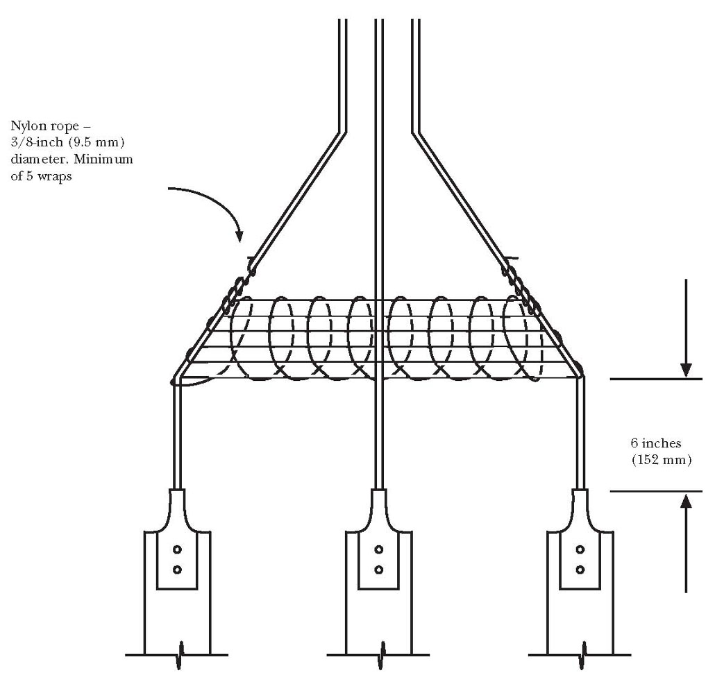
An example of a marking that satisfies this requirement is: “Wrap line cables together with minimal 3/8-inch nylon rope or rope having a minimum tensile strength of 2,000 pounds at (1) 6 inches and 12 inches from the line terminals with five wraps and (2) every additional 6 inches with five wraps or every 1 inch with one wrap.” The drawing in Figure 9.1 may also be provided.
Figure 9.1: Securement of cable
-
SYSTEM COORDINATION
NEC® Section 240.12 concerns electrical system coordination. UL does not evaluate switchboards to determine compliance with the NEC® Section 240.12, since it is not possible to determine upstream and downstream system overcurrent devices that have been selected. It is the responsibility of the system design engineer to specify overcurrent devices for system coordination.
-
VOLTAGE DROP
UL does not evaluate switchboards to determine compliance with voltage drop considerations. It is the responsibility of the design engineer to address any voltage drop considerations in a switchboard system, as needed.
-
CONDUIT ENTRY
Unless indicated otherwise (as noted below), UL evaluates switchboards to determine compliance for the clearance of conductors and conduit entering into the bottom of a switchboard, per NEC® Section 408.5. Acceptability of other conduit entry/exit points can only be determined at the time of final installation.
In order to correlate with NEC® Section 408.5, if the minimum distance between the bottom of the enclosure and any bus bars is less than:
- 8 inches for insulated bus bars, their supports and other obstructions, or
- 10 inches for uninsulated bus bars,
then instructions and drawings showing the intended conduit or raceway locations are (1) supplied with the switchboard section or enclosure or (2) contained in the manufacturer’s catalog (identified by the catalog number or other designation that appears on the switchboard).
-
ENCLOSURE TYPES
A switchboard section or enclosure is provided with a marking that is visible after installation that indicates the enclosure type designation(s). This marking helps inspection authorities to judge whether an enclosure is suitable for a specific environment as mentioned in NEC Section 110.3(A)(1). Enclosure type designations are coordinated with requirements in NEC Section 110.28.
-
MULTIPLE SOURCES
A multiple source switchboard for parallel operation, without synchronization equipment provided integral to the switchboard is provided with the following statement on the installation instructions or factory supplied drawings: “CAUTION – This switchboard is constructed for parallel source applications from multiple sources. Synchronization equipment shall be provided by _________________” or equivalent. The blank is populated with the name of the synchronizing equipment manufacturer.
A switchboard intended to be connected to multiple sources is marked to indicate that both ends of a disconnecting means may be energized. The marking is provided on all covers that give access to the disconnecting means.
-
BARRIERS
In a switchboard section or interior marked as being suitable for uses as service equipment, any uninsulated ungrounded bus bar or terminal on the line side of a service disconnect is isolated by a barrier so that with every service disconnect in the off position, no uninsulated live part is exposed to inadvertent contact while servicing any load terminal, including a neutral load terminal, a branch circuit equipment grounding terminal or the neutral disconnect link. The barrier may contain ventilating openings.
-
SWITCHBOARDS WITH PROVISIONS FOR CORD CONNECTIONS
Switchboards provided with single pole separable connectors (input or output connections) that are not mechanically interlocked are marked:
- “FOR USE BY QUALIFIED PERSONNEL ONLY”, or equivalent, and
- With instructions as to the proper order of connection and disconnection, as noted in the below example:WARNING – Risk of Electric Shock
Plug connection should be in the following order;
1) Equipment grounding conductor connectors;
2) Grounded circuit conductor connectors; and
3) Ungrounded conductor connectors.
Disconnection should be in the reverse order.
This marking is located adjacent to the point of connection.
Switchboards with inlets are marked to indicate the type of derived system that the switchboard is intended to interconnect in accordance with either (A) or (B):
- Switchboards that do not switch the neutral conductor are marked with the following: “WARNING – For Connection of a Nonseparately Derived (Floating Neutral) System Only.”
- Switchboards that switch the neutral conductor are marked with the following: “WARNING – For Connection of a Separately Derived (Bonded Neutral) System Only”
Switchboards with inlets are also marked to indicate the short circuit current rating when the switchboard is powered by a source that is connected through the use of the inlets.
-
FIELD INSTALLATION OF DEVICES
The UL Mark applies to the switchboard as it is originally manufactured when the UL Mark was applied. Authorized use of the UL Mark is the manufacturer’s declaration that the switchboard was originally manufactured in accordance with the applicable requirements. When a switchboard bearing a UL Mark is modified or rebuilt (including being refurbished, remanufactured, reconditioned or renovated) after the UL Mark was applied, UL does not know if the product continues to meet the applicable requirements unless the modification or rebuilding has been specifically investigated by UL. The only exceptions to this are:
- When a UL-certified switchboard has specific markings for field-installed equipment or the replacement of components; or
- When the individual product is addressed through one of the specific programs and is marked as noted below.
Evidence that UL has specifically investigated the modification or rebuilding can only be demonstrated by a product that bears the UL Mark or label of one of UL’s programs for modified or rebuilt equipment, which include:
UL Rebuilt Product Certifications – UL’s rebuilt product certifications cover a wide range of product types. The general Guide Information for each product category with a rebuilt certification program identifies the applicable requirements and the specific marking for products rebuilt under the program. Only rebuilt products that bear the UL Mark together with the word “Rebuilt,” “Refurbished,” “Remanufactured,” “Reconditioned” or “Renovated” have been investigated by UL to the applicable certification requirements.
UL Retrofit Certifications – UL’s retrofit certifications include an investigation of all required component parts, including instructions, for retrofitting specific types of certified products in the field. Products investigated under this program bear a UL Mark together with the product identity including the word “Retrofit.”
UL Field Evaluated Products – For products identified by the Authority Having Jurisdiction, owner, or other regulatory body as being acceptable to evaluate after installation or otherwise outside of the manufacturer’s location, UL’s Field Evaluation program addresses investigation to applicable product requirements based on the specific application and use location for the particular equipment. The specific equipment investigated under this program bears the UL Field Evaluation label.