Dampers – UL Marking and Application Guide
This Marking and Application Guide applies to Dampers for Fire and Smoke Protection
May 2020
PREFACE
Building and fire codes require fire and smoke protection features to safeguard building occupants from fire hazards and hazards associated with smoke and hot toxic gases generated during a fire situation. These model codes provide fire and life-safety for both building occupants and fire fighters/emergency responders during emergency operations. One important aspect of this protection scheme is based on limiting the movement of fire, along with the associated smoke and toxic gases, from traveling throughout the building using a compartmentation approach that creates “fire areas”. This includes requiring fire-resistance-rated assemblies, such as fire walls, fire barriers, fire partitions, shaft enclosures and horizontal assemblies be provided to limit the spread of fire. Building and fire codes also include requirements designed to limit the movement of smoke and toxic gases through the building by requiring smoke barriers and partitions, creating “smoke compartments”. This system of passive protection is an integral part of the overall fire safety approach taken by the model codes.
This marking and application guide provides important information on limiting the spread of fire, smoke and toxic gases by protecting duct penetrations and air-handling openings in fire and smoke rated assemblies. There are five types of dampers recognized by the model codes for this purpose: fire, smoke, combination fire-smoke, ceiling and corridor dampers. UL certifies all five types of dampers in accordance with the requirements in model building, fire, and mechanical codes. These dampers and the applications for which they are certified are covered in detail in this guide. There are also duct protection methods that are an integral part of fire-resistance rated assemblies, and are described within the designs. (See section 3)
For information related to volume control dampers intended for installation in air-handling spaces (plenums) as defined in NFPA 90A, see the UL product category EIMZ. For information on smoke control systems, see NFPA 92. For information on exhaust dampers used in commercial cooking exhaust hoods, see the UL product category YXZR and UL’s Commercial Cooking and Food Service Equipment Marking and Application Guide.
More information on those products is located in UL’s online certifications directory, Product iQTM, available at www.ul.com/PiQ. Product iQ is free to use, but does require a one-time registration.
UL has developed this guide for use by code and inspection authorities, architects, contractors, installers and other interested parties. It is intended to aid in understanding the types of dampers which exist, in association with the applicable codes and standards to facilitate safe, code-compliant installations.
UL Marking and Application Guides are updated as necessary due to new product development, changes in the codes, or the need for clarification. To confirm the current status of any UL Marking and Application Guides, please consult the Code Authorities page of the UL Web site.
- PREFACE
- 1. INTRODUCTION
- 2. DAMPER TYPES
- 3. ALTERNATE TYPES OF PROTECTION FOR DUCT OUTLETS
- 4. DAMPER CODES AND STANDARDS
- 5. INSTALLATION CONSIDERATIONS
- 6. DAMPER SELECTION AND INSTALLATION
- 7. DIAGRAMS OF COMPLETE ASSEMBLIES
- 8. INSPECTION, TESTING and MAINTENANCE
- 9. FIELD SERVICES
- 10. MARKING INFORMATION
- APPENDIX A – CODES AND STANDARDS
1. INTRODUCTION
A. USE OF THIS GUIDE
This guide is intended to assist users to locate, specify or verify the correct type and code compliant UL Listed damper based on the use and installation location.
The model codes require dampers used in these applications to be “listed”. These dampers have been “UL Classified”, which is the terminology used by UL to inform the product has been evaluated for specific functions and applications. “Certified” is another term used by UL to identify that the product has been evaluated by a third party certification organization in accordance with the appropriate required standard. The terms “listed”, “certified” and “classified” as used by UL all meet the definition of “listed” as described in the model codes.
The four-letter code associated with products covered in this marking and application guide is the UL category code designation for that product. Each category code provides a link to the published product GuideInfo for that product and links to the products certified within that category. The product GuideInfo is a technical document which details the scope of the products covered, information relating to limitations or special conditions applying to the product, the requirements used for the investigation of the products and general installation and use information. Product GuideInfo is available in UL Product iQ. The information provided in the product GuideInfo is different from the overview and expanded explanatory information contained in this marking and application guide.
2. DAMPER TYPES
Dampers commonly fall into five types, each with a specific function and end-use application. Types of dampers include fire dampers, smoke dampers, combination fire-smoke dampers, ceiling dampers and corridor dampers. Their functions and performance requirements will vary depending on the damper type.
Additional information is also available in the UL Guide Information for Fire Resistance Ratings (BXUV) in Part III (Floor-Ceilings and Roof-Ceilings), Section 16 – Air Ducts and Protection Systems. Category EMME covers damper types A -D on the following list and type E is covered by CABS:
-
- FIRE DAMPERS
- SMOKE DAMPERS
- COMBINATION FIRE AND SMOKE DAMPERS
- CORRIDOR DAMPERS
- CEILING DAMPERS
See also BZGU for air terminals and BZZU ceiling air diffusers
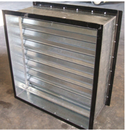
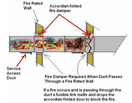
A. FIRE DAMPERS
Fire dampers are designed to close automatically when heat is detected, and are used to restrict the spread of fire where ducts and air transfer openings penetrate fire walls, fire barriers, fire partitions, horizontal assemblies and shaft enclosures. The building codes specify where fire dampers are required, and establish how the fire damper is to be installed in the field.
Fire dampers are available in two types, static fire dampers and dynamic fire dampers. Fire dampers for use in either static systems or dynamic systems are certified by UL with an hourly fire-protection rating, either 1-1/2 or 3 hours.
Fire dampers for use in static systems, as their name implies, are only to be used in duct systems or penetrations where the HVAC system is automatically shut down in the event of a fire.
Fire dampers for use in dynamic systems are required at locations where fan pressure and airflow continue to operate during a fire incident, and as such, the dampers are expected to operate (close) against the air velocity and pressure produced by the system fan. In addition to an hourly fire-protection rating, fire dampers for use in dynamic systems are also provided with an airflow rating which indicates the maximum velocity (damper open) and static pressure (damper closed) for which the damper is designed. Refer to the section in this guide entitled Airflow Ratings for a more detailed explanation of the limitations of the ratings.
Fire dampers are tested as part of fire-resistance rated vertical or horizontal assemblies in accordance with the Standard for Fire Dampers, UL 555, and are listed under (EMME) category. Fire dampers are investigated for use in specific fire-resistive vertical or horizontal assemblies as specified by the installation instructions that are supplied by the product manufacturer. Each listing is specific with respect to (1) construction details of the assembly in which the damper is installed, (2) the hourly fire-protection rating, (3) the damper mounting position (i.e. vertical or horizontal), (4) the maximum size of a single section, and (5) the maximum size of multiple damper sections, In addition, listings of fire dampers for use in dynamic systems will also include the maximum air flow and maximum static pressure for which the damper is listed.
B. SMOKE DAMPERS
 Smoke dampers are used to restrict the movement of smoke where ducts and air transfer openings penetrate assemblies that are designed to restrict the movement of smoke. These devices are installed to operate automatically, controlled by a smoke detection system, and, where required, capable of being positioned from a remote command station.
Smoke dampers may be required where ducts penetrate through smoke barriers or smoke partitions, or at other locations within an engineered smoke control system. Smoke dampers can be used in HVAC systems where the fans are shut down in the event of fire, and can also be used in smoke control systems designed to operate during a fire incident. Smoke dampers are designed to operate against air velocity and fan pressure.
Smoke dampers listed by UL have a leakage class rating that indicates the level of air leakage measured through the damper under test conditions. Leakage ratings are identified as Class Designation I, II or III as shown in the following table. Leakage ratings of smoke dampers are established at a minimum differential pressure of 4 in. water gauge (WG), across the closed damper. Leakage rates may also be established at higher differential pressures, in increments of 2 in. water gauge. The model codes require a Class I or II rated smoke damper.
Maximum Leakage (cfm/ft2)
| Class | 4 In. WG | 6 In. WG | 8 In. WG | 10 In. WG | 12 In. WG |
|---|---|---|---|---|---|
| I | 8.0 | 9.5 | 11.0 | 12.5 | 14.0 |
| II | 20.0 | 24.0 | 28.0 | 31.5 | 35.0 |
| III | 80.0 | 96.0 | 112.0 | 125.0 | 140.0 |
Smoke dampers are also provided with an airflow rating maximum velocity (damper open) and static pressure (damper closed). Refer to the section in this guide entitled Airflow Ratings for a more detailed explanation of the limitations of the ratings.
Smoke dampers are tested as part of vertical or horizontal assemblies in accordance with the Standard for Smoke Dampers, UL 555S, and are Listed under the (EMME) category. Smoke dampers are investigated for use in specific vertical or horizontal assemblies as specific in the installation instructions supplied with the product. Each listing is specific with respect to (1) construction details of the assembly in which the damper is installed, (2) the air leakage rating, (3) the damper mounting position (i.e. vertical or horizontal), (4) the minimum and maximum sizes of a single section, and (5) the maximum size of multiple damper sections.
C. COMBINATION FIRE-SMOKE DAMPERS
Combination fire-smoke dampers are used to restrict both the spread of fire and movement of smoke where ducts and air transfer openings penetrate assemblies that are designed to restrict the passage of both fire and smoke. Dampers that are marked as combination dampers comply with both the Standard for Fire Dampers, UL 555 and the Standard for Smoke Dampers, UL 555S, are listed under the (EMME) category.
D. CORRIDOR DAMPERS
Corridor dampers are combination fire-smoke dampers that have been specifically evaluated for mounting only in ceilings of fire-resistance-rated corridors, where the corridor ceiling is permitted by the building code to be constructed as required for the corridor walls (sometimes referred to as “tunnel corridors”).
Corridor dampers are tested horizontally as installed in specific tunnel corridor ceiling constructions in accordance with both the Standard for Fire Dampers, UL 555 and the Standard for Smoke Dampers, UL 555S, and are covered under the (EMME) category. Corridor dampers are investigated for both a fire-resistance rating of 1 hour, and a Class I or II leakage rating as defined under SMOKE DAMPERS. Leakage ratings of corridor dampers are determined at an elevated temperature 250°F or 350°F. Leakage ratings of corridor dampers are established based on test conditions using air. Corridor dampers have also demonstrated acceptable closure performance when subjected to 150 fpm velocity across the face of the damper during fire exposure. Corridor dampers are investigated for use in specific horizontal ceiling constructions as specified in the installation instructions supplied with the product.
Each listing is specific with respect to (1) construction details of the ceiling in which the damper is installed,(2) the hourly fire-protection rating, (3) the damper leakage Class, (4) the minimum and maximum size of a single damper section.
E. CEILING DAMPERS
Ceiling dampers (referred to as ceiling radiation dampers in the International Building Code) are intended to function only as a heat barrier to limit heat transfer, into the concealed space of a fire-resistance-rated floor-ceiling or roof-ceiling assembly where ducts or air transfer openings are made only through the ceiling membrane that is part of the fire-resistance rated assembly. As such, the building codes have not defined the use of these products in so far as their use as smoke barriers, nor do the UL certifications include the use of these products to limit the migration of smoke or passage of flame. Ceiling membranes are part of floor-ceiling or roof-ceiling fire resistance rated assemblies that have been evaluated in accordance with the Standard for Fire Tests of Building Construction and Materials, UL 263. The construction of floor-ceiling or roof-ceiling assemblies evaluated by UL are published in the BXUV product category. The GuideInfo provides additional details regarding the design, construction, and use of these assemblies.
Ceiling dampers are designated as either static or dynamic and are evaluated for use in HVAC systems. Static ceiling dampers are used in duct systems where the airflow is automatically shut down, typically by activation of area smoke detection or the automatic fire alarm system. Dynamic ceiling dampers are required at locations in which fan pressure and airflow remain in operation during a fire incident. Dynamic dampers for use in HVAC systems are also provided with an airflow rating which indicates the maximum velocity (damper open) and static pressure (damper closed) for which the damper is designed, similar to the ratings provided for a traditional listed (EMME) smoke damper.
Although these ratings relate to individual dynamic ceiling damper models it is important to note that both static and dynamic ceiling dampers do not have an assigned hourly fire-resistance rating. Rather, ceiling dampers are tested as components of UL fire-resistance designs and are intended to be installed following the manufacturer’s installation instructions provided with the product, and the specifications detailed in each UL fire-resistance design. Ceiling dampers labeled for use in dynamic systems are also suitable for use in static systems where they have been investigated as a component of the floor/ceiling or roof/ceiling fire-resistance design.
Ceiling dampers that are tested and listed in combination with specific permanently installed fan models shall not be required to be labeled as dynamic ceiling dampers. Both the individual ceiling damper model installation instructions as well as UL Product iQ will indicate which model ceiling dampers are permitted to be used with the appropriate model fans. These combinations of ceiling dampers and permanently installed fans are tested with the damper open and the fan running at the beginning of the test, demonstrating that both the fan uses some sensing means to shut down, and that the damper can fully close. This ensures that a static condition will be established during the event, and removes the need for these combinations to require to be labeled for dynamic ceiling dampers.
Methods of evaluation for ceiling dampers
Ceiling dampers are evaluated by UL using one of two methods as explained below.
-
Method 1.
Ceiling Dampers For Use In Lieu Of Hinged Door Type Dampers – Where floor-ceiling or roof-ceiling designs contain air ducts and specify the use of hinged door type dampers over each duct outlet, ceiling dampers are investigated for use in lieu of the specified hinged door type dampers.
The basic Standard used to evaluate ceiling dampers for use in lieu of hinged door type dampers is The Standard for Ceiling Dampers, UL 555C. It is important to note that ceiling dampers covered for this specific application are only intended for use in those UL fire resistance designs that indicate the use of a hinged door type damper in the design. This information is located in the UL Product iQ database in the text and drawings of the specific UL fire resistance designs. The UL certification of ceiling dampers does not cover the products for general installation in any floor-ceiling or roof-ceiling design. Examples of this scenario can be found in UL Fire Resistance Design Nos. G214, G526 and L201.
Ceiling dampers evaluated in this fashion are covered under the product categories Air Terminal Units (BZGU), Ceiling Air Diffusers (BZZU) and Ceiling Dampers (CABS). The Classification text for ceiling dampers evaluated in this manner will specify the types of designs in which they may be used and the conditions under which they may be substituted for the hinged door type dampers.
-
Method 2.
Ceiling Dampers For Use In Specific Fire Resistance Designs – Alternatively, some floor/ceiling or roof/ceiling fire resistance rated assemblies specify one or more specific ceiling dampers. Dampers covered by this method of evaluation are generally tested along with the specific design construction in accordance with the Standard for Fire Tests of Building Construction and Materials, UL 263, in addition to UL 555C. Applicable information describing the installation of ceiling dampers for this application, include a reference to the specific ceiling damper model, an indication that the fire resistance design ratings were developed under conditions employing air movement and the maximum qualified velocity rating, is included in the text and drawings for the specific designs in UL Product iQ. Examples of this scenario can be found in the follow UL Fire Resistance Designs. L501, L521 and M557.
Ceiling dampers evaluated for use in specific fire resistance rated designs are covered under the Ceiling Dampers (CABS) category. The UL certification for the ceiling dampers will make reference to the specific floor-ceiling or roof-ceiling designs in which they are intended to be installed as well as the applicable static or dynamic designation. Dynamic ceiling dampers are also marked with the maximum air flow and closure pressure for which the damper has been investigated.
The application of ceiling dampers are distinctly different than the applications of the other types of dampers. Refer to the section in this Guide entitled Horizontal Dampers under Installation Considerations for a detailed explanation of these differences.
3. ALTERNATE TYPES OF PROTECTION FOR DUCT OUTLETS
Under certain conditions, duct openings through the ceiling membrane of a fire resistance-rated ceiling may be protected using either Duct Protection Systems A or B, as described in the Guide Information for Fire Resistance Ratings – ANSI/UL 263 (Product Category BXUV). Below is information describing the use of Duct Outlet Protection Systems A and B.
A. DUCT OUTLET PROTECTION SYSTEM A (As Permitted by the Individual Designs within BXUV)
![]()
Item 1 – Steel Duct
Item 2 – UL Certified Glass Fiber Duct Lining
Item 3 – UL Certified Acoustical Lay-in Panel
Item 4 – Ceramic Paper
Duct Outlet Protection System A is only to be used where specified in an individual UL Fire Resistance Design. This method of construction consists of a combination of protecting the inside of rectangular shaped steel ducts with a minimum 1 in. thick, 3.0 to 5.0 pcf glass fiber duct lining, applying an acoustical ceiling lay-in panel on top of the duct, and protecting the duct outlet with ceramic paper where specified in the individual design. See the Guide Information for Fire Resistance Ratings – ANSI/UL 263 (category BXUV) for further details on the use of this protection method.
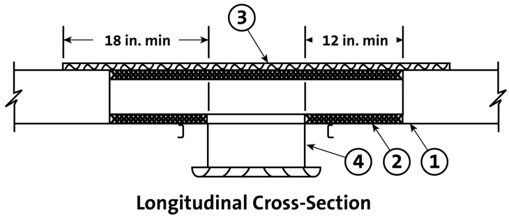
B. DUCT OUTLET PROTECTION SYSTEM B (Permitted where a steel duct with a hinged-door damper is described in a fire resistance-rated design)
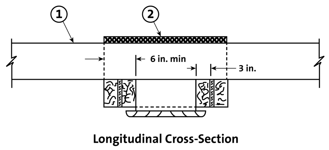
![]()
Item 1 – Steel Air Duct
Item 2 – UL Certified Mineral Wool Batts
Item 3 – Ceramic Paper
Duct Outlet Protection System B may be used in any design which contains a steel duct with the duct outlet protected by a hinged door damper, for equal or smaller outlet size. This system has been investigated for effectiveness in restricting the transfer of heat into the concealed space above the ceiling. This method of construction consists of protecting the outside of rectangular shaped steel ducts with a minimum 1-1/4 in. thick, 3.5 to 8.0 pcf mineral wool batts and protecting the duct outlet with ceramic paper where specified in the individual design. See the Guide Information for Fire Resistance Ratings – ANSI/UL 263 (category BXUV) for further details on the use of this protection method.
4. DAMPER CODES AND STANDARDS
Dampers are intended to be installed in accordance with locally enforced building, fire and life safety codes, and in accordance with standards referenced in those codes. In many cases these codes require dampers to be listed and labeled in accordance with UL 555, UL 555S and/or UL 555C.
Detailed information on damper related codes and standards can be found in Appendix A.
UL certifies damper related products under the following product categories.
| Category Code | Category Name | Standard Used |
|---|---|---|
| BZGU | Air Terminal Units | UL 263 |
| BZZU | Ceiling Air Diffusers | UL 263 and UL 555C |
| CABS | Ceiling Dampers | UL 263 and UL 555C |
| EMME | Dampers for Fire Barrier and Smoke Applications | UL 555, UL 555S |
5. INSTALLATION CONSIDERATIONS
Model codes include requirements to restrict the spread of fire and smoke through a building using assemblies with specific requirements concerning their construction and placement. Openings in these assemblies must be protected in a manner which compliments the intent of the assembly.
In order to function properly, a damper must be installed in accordance with the applicable code requirements and its listing as well as the manufacturers installation instructions.
An approved means for proper access to the damper for inspection, testing and maintenance must be provided for each Damper installation
Manufacturer’s installation instructions for dampers are reviewed in detail as part of their certification in accordance with the applicable Testing Standards. It is recommended that these manufacturer’s instructions be included with the construction document submitted with a building permit application for plan review and approval by the code authority. Instructions are required to be shipped with each Damper for use by the installation contractor at the construction site. Fire or smoke dampers are not to be installed using firestopping materials unless this method of installation is explicitly permitted by the manufacturer’s installation instructions provided with the damper.
Below are some installation considerations which should be considered prior to installation of the damper.
A. DAMPERS IN HORIZONTAL ASSEMBLIES
Since there are multiple types of dampers for use in protecting openings in horizontal assemblies, it is important to carefully consider the proper damper for each application. The correct damper depends on the application.
As a general rule, vertical ducts rising through fire rated floors are to be protected by fire rated shaft enclosures. As the fire resistive shaft rises through the structure, it is not necessary to protect the opening at the floors the duct passes through because the duct is located in a fire rated shaft. The shaft should be penetrated horizontally so that vertical dampers can be used to protect the penetration through the shaft.
The model codes contain several exceptions to the shaft enclosure requirements. Where a vertical duct penetrates a horizontal assembly without a shaft enclosure, a horizontal fire damper is required. If the horizontal assembly is also a smoke barrier, a combination fire-smoke damper is required.
When the duct penetrates through the membrane ceiling of a fire-resistance-rated floor-ceiling or roof-ceiling assembly, but not through the floor or roof, then a ceiling damper is used. The intent of the lower ceiling membrane is to retard the passage of heat into the concealed space. As such, the ceiling damper must likewise retard the passage of heat. Refer to the section in this guide entitled Ceiling Dampers under Damper Types for a detailed explanation of the limitations of the certifications applied to ceiling dampers.
Openings entirely through the ceiling of a tunnel corridor, where the ceiling is constructed as required for the walls, are protected with corridor dampers. These dampers must restrict the spread of fire and the movement of smoke through the ceiling assembly.
In all cases, the damper manufacturer’s installation instructions depict the appropriate installation parameters and limitations.
B. INSTALLATION INSTRUCTIONS
Each damper shipment is supplied with a copy of the installation instructions appropriate for the specific damper model. These instructions are an integral part of the UL certification on the dampers as UL reviews the instructions as part of the damper listing process. The instructions contain the information necessary to properly install the damper as well as limitations on the installation of the product such as the type of floor or wall construction that is required for the correct installation.
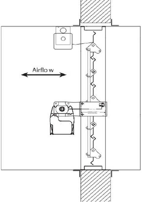
Example of a common damper installation:
The damper shall be secured in the opening using retaining angles. Ducts are attached to the damper sleeve using breakaway methods. A remote sensor device may activate the damper actuator.
Some manufactures elect to provide basic instructions that cover only common installations, and then rely on supplemental instruction pages that cover unique installation scenarios. As with the basic installation instructions, the supplemental instructions are also an integral part of the UL certification program as the supplemental instructions are also reviewed by UL during the product evaluation.
C. MULLIONS
The certifications covering fire dampers are limited to the single and/or multiple assembly sizes that are evaluated. The size limitations are specified in the published certification information for each damper model.
In certain circumstances, steel mullions can be used to divide a large wall or vertical partition opening into smaller individual openings, allowing fire dampers for use in static systems to be sized and installed within the limitations of the certification. These mullions are generally fabricated in the field. Damper manufacturers can provide installation details covering the fabrication, installation and use of mullions.
Because airflow ratings of fire dampers for use in dynamic systems and combination fire-smoke dampers are size dependent, the use of the mullions discussed herein are only intended for application with fire dampers for use in static systems. Further, the mullions are limited to use in vertical partitions.
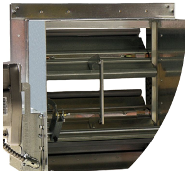
D. DAMPER ACTUATORS
Smoke dampers, corridor dampers, and combination fire-smoke dampers are equipped with factory installed electric or pneumatic actuators which can be controlled remotely to open and close the damper blades. The airflow and pressure ratings marked on the dampers are dependent upon the particular combination of damper type, actuator type and linkages between the damper blades and actuator. As such, field mounting or substitution of actuators is not covered within the scope of the UL certification of the product. However, this does not necessarily preclude replacement of actuators in the field.
Like any appliance, field servicing of these products is not covered under the scope of the UL certification program. As with any part of the damper, it is expected that replacement of actuators in the field be done in accordance with the damper manufacturer’s normal field servicing program.
E. DETECTORS AND SMOKE DAMPERS
Smoke dampers may be required by the model codes or installation codes to be closed when smoke detectors operate.
Duct type smoke detectors have a minimum and maximum airflow rating. The ratings must be compatible with the ratings of the smoke damper. Smoke dampers have a minimum airflow rating of 0 fpm and a maximum airflow rating as marked on the damper. Duct type smoke detectors typically have a minimum airflow rating of 300-500 fpm. However, there are duct type smoke detector models available that are rated for use at zero airflow. For HVAC systems that are shut down in the event of a fire, smoke dampers equipped with duct type smoke detectors with a greater than zero minimum airflow rating, may also need to be controlled with a device that will close the damper in the event that the damper is in the open position when the fans are shut down.
F. AIRFLOW RATINGS
Dynamic fire dampers, smoke dampers and combination fire-smoke dampers are marked with airflow and closure pressure ratings. These ratings represent the maximum airflow and closure pressure ratings tested for that product. The closure pressure rating is not the pressure drop across an open damper.
Maximum airflow ratings are marked in 1000 fpm increments with a minimum rating of 2000 fpm. Maximum closure pressure ratings are marked in increments of 2 in. WG with a minimum closure pressure rating of 4 in. WG.
The end user needs to analyze the expected airflow across an open damper in the design of the HVAC system. There are many permutations of opened and closed dampers that may occur under different fire scenarios. The airflow rating for a particular application is not necessarily one that matches the normal design airflow within the ducts. Some dampers may become fully isolated against the fan pressure. Authorities having jurisdiction should field-test various combinations of opened and closed dampers to represent the worst expected condition across the damper.
Similarly, closed dampers may be isolated against the fan pressure and have a pressure higher than the rating. These dampers would be unable to be opened. This has significance for system designs that require dampers to be opened under fire and/or smoke conditions.
6. DAMPER SELECTION AND INSTALLATION
In order to properly select a UL Classified damper one needs to know and understand the building design criteria and applicable model code requirements. The following steps provide a systematic approach that can be followed to provide a safe, code compliant installation. This process can also be used by code authorities during the building approval process.
-
- Determine the size and location of dampers – A number of factors dictate the design of the building heating, ventilation and air conditioning system. These may be driven by code requirements or by the needs of the occupants and tenants. Prior to selecting the appropriate dampers, the size and location of the basic system needs to be identified, and size and routing of the supply and return ducts needs to be determined.
- Confirm if dampers are required to limit the passage of fire, smoke, or both – The fire safety system embodied in building code requirements is based on the use of walls and partitions, and horizontal floor-ceiling and roof-ceiling assemblies designed to contain fires and the resulting smoke and products of combustion within certain areas of the building through compartmentalization. The codes require HVAC openings to be protected to restrict the passage of fire and smoke. One of the options within the codes to protect these openings in walls and horizontal assemblies is the use of dampers which are required to comply with specific UL standards, and to have certain ratings.To determine the standards and ratings these dampers must meet, one first needs to determine if the walls and horizontal assemblies in which they installed are covered by code requirements.
-
-
- Fire Walls, Fire Barriers and Fire Partitions – These are all fire-resistance-rated vertical assemblies designed to restrict the spread of fire in which continuity is maintained. However the hourly rating, construction, extent of continuity and support for these assemblies varies. Ducts and air transfer openings in these assemblies are required to be protected against the spread of fire in accordance with the requirements included in the code. As such, the code requires the use of fire dampers in these openings. Fire dampers installed in assemblies having a fire-resistance rating of less than 3 hours shall have an hourly fire-protection rating of 1-1/2 hours. Fire dampers installed in assemblies having a fire-resistance rating of 3 hours or greater shall have an hourly fire-protection rating of 3 hours.
- Horizontal Assemblies – Horizontal assemblies are fire-resistance-rated floor-ceiling and roof-ceiling assemblies designed to restrict the spread of fire in which continuity is maintained. However, the hourly rating, construction and support for these assemblies varies. Ducts which pass through these assemblies are required to be protected against the spread of fire in accordance with the requirements included in the code. As such, the code requires the use of fire dampers in these openings. Fire dampers installed in horizontal assemblies having a fire-resistance rating of less than 3 hours shall have an hourly fire-protection rating of 1-1/2 hours. Fire dampers installed in assemblies having a fire-resistance rating of 3 hours or greater shall have an hourly fire-protection rating of 3 hours. Ducts and air transfer openings which penetrate only the ceiling membrane of a floor-ceiling or roof-ceiling assembly where the ceiling is providing the fire protection are required to be protected so as to limit the passage of heat into the concealed space of the assembly. As such, the code requires the use of ceiling dampers in these openings.
- Shaft Enclosures – Shaft enclosures are constructed using fire-resistance-rated fire barriers and horizontal assemblies designed to restrict the spread of fire and movement of smoke in which continuity is maintained. Ducts and air transfer openings in shaft enclosures are required to be protected against the spread of fire and movement of smoke in accordance with the requirements included in the code. As such, the code requires the use of individual fire and smoke dampers, or a combination fire-smoke damper. To determine the appropriate ratings for dampers in shaft enclosures, refer to the specific code requirements covering ducts and air transfer openings in shaft enclosures. This will include a leakage rating in conjunction with an hourly fire-protection ratings.
- Smoke Barriers and Smoke Partitions – Smoke barriers are continuous membranes, either vertical or horizontal, such as a wall, floor or ceiling assembly, that are designed to restrict the movement of smoke through a building. In addition to restricting the movement of smoke, smoke barriers have a fire-resistance rating as specified in the code. Smoke partitions are continuous vertical membranes, such as a wall, that are also designed to restrict the movement of smoke through a building, but are not required to have a fire-resistance rating. Ducts and air transfer openings in smoke barriers are required to be protected against the spread of fire and movement of smoke in accordance with the requirements included in the code. As such, the code requires the use of individual fire and smoke dampers, or a combination fire-smoke damper in these assemblies. Openings in smoke partitions are required to be protected to restrict the movement of smoke in accordance with the requirements included in the code. As such, the code requires the use of smoke dampers in these openings. To determine the appropriate ratings for dampers in these assemblies, refer to the specific code requirements covering ducts and air transfer openings in these wall assemblies. This will include a leakage rating for dampers used in smoke barriers and partitions, in conjunction with hourly fire-protection ratings for dampers in smoke barriers.
- Corridors – Corridors are constructed using fire-resistance-rated fire partitions designed to restrict the spread of fire and movement of smoke in which continuity is maintained. However, the hourly rating, construction and support for these assemblies varies. Ducts and air transfer openings in these assemblies are required to be protected to resist the spread of fire and movement of smoke in accordance with the requirements included in the code. As such, the code requires the use of combination fire-smoke dampers. To determine the appropriate ratings for dampers in corridors, refer to the specific code requirements covering ducts and air transfer openings in these assemblies. This will include a leakage rating in conjunction with hourly fire-protection ratings. Ducts and air transfer openings which penetrate only the ceiling of a corridor where the ceiling is constructed as required for the walls, shall be protected to resist the spread of fire and movement of smoke with a corridor damper.
-
-
- Determine if static or dynamic fire dampers are needed – If fire dampers are determined to be required in the HVAC system, determine if the system is to be automatically shut down in the event of a fire. If it is, either static or dynamic fire dampers may be utilized. If the system is not shut down, dynamic fire dampers shall be specified. The specified dynamic fire damper must have a maximum airflow and static pressure consistent with the design of the HVAC system.
- Determine the type of actuator to be utilized – Smoke dampers and combination fire-smoke dampers are equipped with factory installed electric or pneumatic actuators which remotely control the dampers. The airflow and pressure ratings are dependent on the particular combination of damper type, actuator type, and linkage between the damper blades and the actuator. The specified damper and actuator combination specified must have a maximum airflow and static pressure consistent with the design of the HVAC system.
- Identify the barrier construction – Once the size, location, type, rating, actuator and airflow requirements for the dampers are established, the next step is to identify the construction of the barriers into which they will be mounted. It is imperative that the barrier construction match the barrier construction which is specified in the damper installation instructions.If ceiling dampers are required, it is important to know the UL Design Number which is being used to identify the fire-resistance rated floor-ceiling or roof-ceiling assembly. If a damper is not specified in the design being utilized, no HVAC penetrations of the ceiling membrane are permitted. If an HVAC penetration is permitted, there are two methods by which ceiling dampers are specified in the designs. First, if a hinged door type damper is specified in the design, then either the hinged door type damper may be used, or a listed Air Terminal Units (BZGU), Ceiling Air Diffusers (BZZU) or Ceiling Dampers (CABS) may be substituted for the hinged door type damper in accordance with the provisions of the listings. It is imperative that the ceiling damper selected be used as specified in its listing. Second, if one or more specific ceiling damper(s) is specified by manufacturer and a specific model number, then only the specified damper(s) can be used and it must be used in accordance with the provisions stated in the design and in its listing.As an alternate to the use of a listed Air Terminal Units (BZGU), Ceiling Air Diffusers (BZZU) or Ceiling Dampers (CABS), Duct Outlet System B may be used in accordance with the provisions of the Guide Information for the Fire Resistance Ratings – ANSI/UL 263 (BXUV) category. Duct Outlet Protection System B may be used in any design which contains a steel duct with the duct outlet protected by a hinged door damper, for equal or smaller outlet sizes. Duct Protection System A may only be used when specified in the individual design.
- Putting it all together – In order to provide for a damper installation that complies with applicable code requirements it is important to identify the size, location, type, rating, actuator, airflow and pressure requirements, along with the specific type of construction in which the damper will be installed. This information can then be used to identify the specific dampers required using UL ProductiQ in conjunction with the manufacturer’s installation instructions.Care should be taken to verify that the dampers are installed in accordance with the manufacturer’s installation instructions, and in accordance with NFPA 90A, NFPA 80 and NFPA 105 requirements.
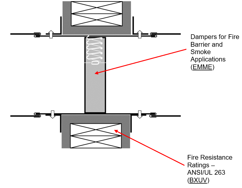
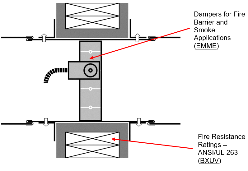
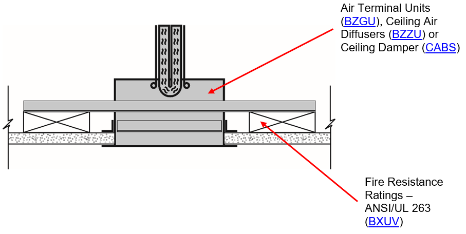
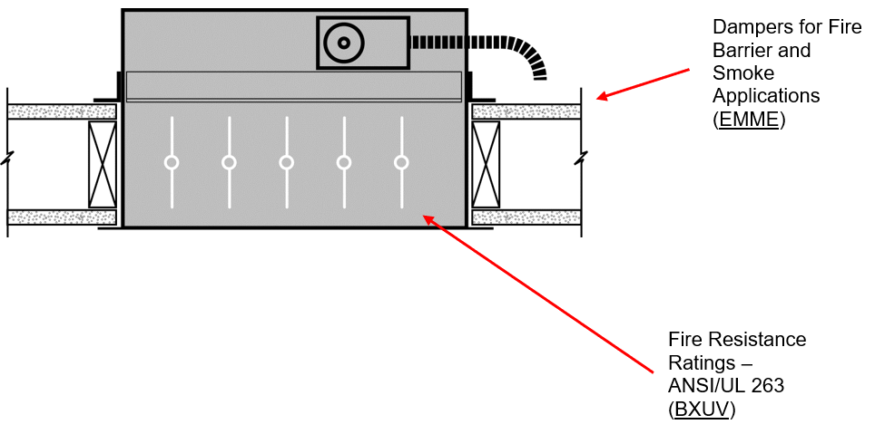
7. DIAGRAMS OF COMPLETE ASSEMBLIES
The following diagrams identify the components that make up complete assemblies, along with links to the guide information for the various product categories. Refer to Appendix for a complete list of related product categories.
8. INSPECTION, TESTING and MAINTENANCE
Like any mechanical device, dampers require periodic maintenance to ensure continued proper operation. The level of maintenance required is dependent on several factors including the product manufacturer’s and system designer’s recommendations, code requirements, and the complexity of the system in which the damper is installed.
The International Fire Code (IFC) and the International Property Maintenance Code (IPMC) and NFPA 1, The Fire Code, require dampers to be inspected and maintained in accordance with NFPA 80, Standard for Fire Doors and Other Opening Protectives and NFPA 105, Standard for Smoke Door Assemblies and Other Opening Protectives. In addition, any damaged products protecting duct and air transfer openings are required to be either repaired, restored or replaced.
NFPA 80 also requires the damper manufacturer’s maintenance instructions to be maintained on site and requires documentation of all required testing and maintenance.
Dampers with fusible links:
The fusible links used in fire dampers are certified to UL 33, Standard for Heat Responsive Links for Fire-Protection Services, temperature classifications and ratings.
NFPA 80 covers the required inspection and testing of dampers and provides the testing frequency required for dampers. Dampers must be tested and inspected 1 year after initial acceptance testing, and then the test and inspection frequency for dampers is every 6 years in a hospital, and every 4 years for all other buildings, thereafter.
Where a fusible link is installed on a combination fire/smoke damper, the link must be removed for testing the damper for full closure, simulating a fire condition per the requirements and frequencies of NFPA 80. The fusible link must be reinstalled after testing is complete.
If a fusible link appears to be damaged or painted when inspected, it must be replaced with a listed link that is functionally equivalent and has the same temperature and load rating.
Periodic maintenance of dampers should include the following:
-
-
- Removal of debris buildup from the damper and surrounding area
- Manual cycling of dampers released by fusible links
- Cycling of damper and actuator assemblies
-
Additional information on periodic testing can be found in the model codes and installation standards.
9. FIELD SERVICES
A. FIELD ENGINEERING SERVICES
Situations may be encountered where determining if a product has been listed by a third-party organization is not possible. Other situations may present a product bearing a listing label that may have been modified in the field, the question then becomes whether or not the product still complies with the applicable standard(s). UL offers field engineering services that provides data that can assist in making the decision whether to accept the product and/or approve the installation. Anyone directly involved with a product – including manufacturers, owners, contractors, and regulatory authorities – can request a field inspection or field evaluation. Detailed information for these programs can be found on UL’s Web site at www.ul.com/field.
B. FIELD-MODIFIED OR REBUILT EQUIPMENT
Both NFPA 80 and NFPA 105 has specific requirements for field modification to a damper. These standards specify that any modification made to the damper shall be in accordance with the damper manufacturer’s installation instructions and its listing. Where the field modification includes adding the capability for remote inspection, the position indicator devices and monitoring equipment shall be tested for functionality immediately following the modification.
An authorized use of the UL Mark is the manufacturer’s declaration that a product was manufactured in accordance with the applicable certification requirements, and was in compliance with those requirements when it was shipped from the factory. When a product bearing a UL Mark is modified or rebuilt (including being refurbished, remanufactured, reconditioned or renovated) after it leaves the factory where the UL Mark was applied, UL does not know if the product continues to meet the applicable requirements unless the modification or rebuilding has been specifically investigated by UL. The only exceptions to this are when a UL-certified product has specific markings for field-installed equipment or the replacement of components, or when the individual product is addressed through one of the specific programs noted below.
Evidence that UL has specifically investigated the modification or rebuilding can only be demonstrated by a product that bears the UL Mark or label of one of UL’s programs for modified or rebuilt equipment, which include:
UL Rebuilt Product Certifications — UL’s rebuilt product certifications cover a wide range of product types. The general Guide Information for each product category with a rebuilt certification program identifies the applicable requirements and the specific marking for products rebuilt under the program. Only rebuilt products that bear the UL Mark together with the word “Rebuilt,” “Refurbished,” “Remanufactured,” “Reconditioned” or “Renovated” have been investigated by UL to the applicable certification requirements.
UL Retrofit Certifications — UL’s retrofit certifications include an investigation of all required component parts, including instructions, for retrofitting specific types of certified products in the field. Products investigated under this program bear a UL Mark together with the product identity including the word “Retrofit.”
UL Field Evaluated Products — For products identified by the Authority Having Jurisdiction, owner, or other regulatory body as being acceptable to evaluate after installation or otherwise outside of the manufacturer’s location, UL’s Field Evaluation program addresses investigation to applicable product requirements based on the specific application and use location for the particular equipment. The specific equipment investigated under this program bears the UL Field Evaluation label.
10. MARKING INFORMATION
Model codes and regulations may require certain products to be “Listed”, or “Listed and Labeled”. Products that UL has certified for use in applications where “listing” or “listing and labeling” are required in the code include a UL Certified, a UL Listed, or a UL Classified Mark. Collectively, these are referred to by UL in this Guide as marks. Products bearing any of these UL marks comply with the definition of a listed product in the code, and should be considered to be listed.
A. UL MARKS
UL Certified products are eligible to bear one of the following Certification Marks, namely the UL Certified Mark, UL Listing Mark, or UL Classification Mark. Refer to product category guide information for specific marking requirements. Products not bearing a UL Mark are not considered to be UL Certified. For more information visit our UL Marks for Code Authorities page.
UL Certified Mark
Here are some examples of the UL Marks you may encounter:
UL Listing Mark

UL Classification Mark

APPENDIX A – CODES AND STANDARDS
A. MODEL CODES
Dampers have been investigated for installation in accordance with the following model codes:
-
-
- The International Building Code (IBC)
- The International Fire Code (IFC)
- The International Mechanical Code (IMC)
- NFPA 1 – Fire Code
- The NFPA 101 – Life Safety Code
- The NFPA 5000 – Building Construction and Safety Code
-
These codes specify the locations in which dampers are required to be installed, the applicable ratings (i.e. hourly fire-protection rating or air leakage rating) required for each installation, the standards with which the products must comply and the related installation and maintenance requirements and applicable maintenance standards.
B. INSTALLATION STANDARDS
These installation standards specify the locations in which these products are to be installed, the ratings required for each installation, the standards with which the products must comply, the related installation standards, and other details.
-
-
- NFPA 90A – Standard for the Installation of Air-Conditioning and Ventilating Systems
- NFPA 80 – Standard for Fire Doors and Other Opening Protectives
- NFPA 105 – Standard for Smoke Door Assemblies and Other Opening Protectives
-
As compared to model codes, which generally describe where dampers are to be installed, installation standards provide more detailed information on how the products are intended to be installed and maintained. Model codes often require dampers to be installed in accordance with installation standards, such as NFPA 90A, NFPA 80 and NFPA 105. A brief summary of these standards is noted below.
NFPA 90A – NFPA 90A is the Standard for the Installation of Air-Conditioning and Ventilating Systems. It regulates the installation, control and acceptance testing of fire, smoke, combination fire-smoke and ceiling dampers used to protect ducts and air transfer openings in walls, floors, and ceilings against the spread of fire and smoke within, into, or out of buildings. The standard addresses products that have been subjected to standardized fire tests, including UL fire and smoke leakage tests.
The installation requirements of NFPA 90A include topics such as where dampers are required, testing requirements, rating requirements, installation requirements and requirements for maintenance in accordance with NFPA 80, the Standard for Fire Doors and Other Opening Protectives, and NFPA 105, the Standard for Smoke Door Assemblies and Other Opening Protectives. The control requirements of NFPA 90A include provisions for manual and automatic control of smoke and combination fire-smoke dampers. Acceptance testing shall demonstrate the damper functions as intended prior to occupancy of the building.
NFPA 80 – NFPA 80 is the Standard for Fire Doors and Other Opening Protectives. It regulates the installation, operational testing, periodic inspection and maintenance of fire, combination fire-smoke and ceiling dampers used to protect ducts and air transfer openings in walls, floors, and ceilings against the spread of fire within, into, or out of buildings. The standard addresses products that have been subjected to standardized fire tests, including UL fire tests.
The installation requirements of NFPA 80 include topics such as damper location, listing and labeling requirements, preparation of openings, securement, access to fusible links and serviceability. Operational test shall demonstrate the damper is installed and functions as intended. Periodic inspection and testing requirements include the required inspection and testing, the required frequency and the required documentation. The maintenance requirements include topics such as the changes in the airflow and noise from the duct, lubrication and required documentation.
Combination fire-smoke dampers are also required to comply with NFPA 105, the Standard for Smoke Door Assemblies and Other Opening Protectives.
NFPA 105 – NFPA 105 is the Standard for Smoke Door Assemblies and Other Opening Protectives. It includes requirements for smoke and combination fire-smoke dampers used to restrict the movement of smoke through duct assemblies in order to maintain a tenable environment. It does this by regulating the installation, operational testing, periodic inspection and maintenance of these dampers. It is also applicable to dampers intended to restrict the passage of smoke through ducts and for dampers used in smoke control systems.
The installation requirements of NFPA 105 include topics such as damper location, damper actuator and linkage, access to fusible links and serviceability. The operational test shall demonstrate the damper is installed and functions as intended. Periodic inspection and testing requirements include the required inspection and testing, the required frequency and the required documentation. The maintenance requirements include topics such as changes in the airflow and noise from the duct, lubrication and required documentation.
Combination fire-smoke dampers are also required to comply with NFPA 80, the Standard for Fire Doors and Other Opening Protectives.
For more information please visit the Code Authorities page.
Dampers Marking and Application Guide UL and the UL logo are trademarks of UL LLC ©2021